The ω-SQUIPT as a tool to phase-engineer Josephson topological materials
Multi-terminal superconducting Josephson junctions based on the proximity effect offer the opportunity to tailor non-trivial quantum states in nanoscale weak links. In a collaboration between the theory groups of Sebastian Bergeret at the CFM and Yuli Nazarov at the Delft University of Technology, together with the experimental group of Francesco Giazotto in Pisa, a three-terminal Josephson interferometer has been analyzed. Tunneling spectroscopy measurements reveal transitions between gapped (that is, insulating) and gapless (conducting) states that are controlled by the phase configuration of the three superconducting leads connected to the junction. These transitions are of topological origin: a gapless state necessarily occurs between two gapped states of different topological indices, in much the same way that the interface between two insulators of different topologies is necessarily conducting. The topological numbers that characterize such gapped states are given by superconducting phase windings over the two loops that form the Josephson interferometer. As these gapped states cannot be transformed to one another continuously without passing through a gapless condition, they are topologically protected. The findings of this work are pivotal for enabling phase engineering of different and more sophisticated artificial topological materials.

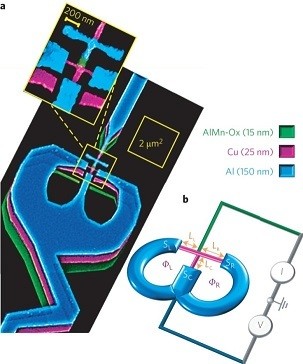
Figure: (a) False-color tilted scanning electron micrograph of a typical ω-SQUIPT. The inset highlights the core of the interferometer: a nanosized T-shaped proximised Cu weak link (magenta) in clean metallic contact with two Al superconducting loops (blue). The area of each loop is around 2µm2. The central part of the weak link is tunnel-coupled to a ∼100-nm-wide Al0.98Mn0.02 normal metal probe (green) via a partial oxidization of the AlMn. The replica structures resulting from the shadow-mask evaporation process are also visible.(b) The measurement set-up. The current flowing through the circuit is indicated by I, and V is the voltage drop across the interferometer. LL, LC and LR denote the lengths of the three arms of the weak-link.


